Design of a GMSK Receiver
P&D Electronics and Chip Design · KU Leuven · 2025
A complete GMSK receiver covering the analog, digital, and mixed-signal domains, designed in a team of four in TSMC's 65 nm technology. The receiver decodes a 100 bit/s Varicode message from a carrier around 20 kHz, down to an SNR of 17.8 dB. The analog front-end amplifies the 1 to 100 mV input with an eleven-level variable gain amplifier and digitizes it with a 4-bit flash ADC. I was responsible for the digital part, which takes it from there and is the focus of this page.
The Digital Demodulator
The ADC's thermometer code is converted to binary by a fat-tree encoder and quadrature-downmixed at 51.2 kHz against an NCO. Integrate-and-dump decimation brings the I and Q paths down to 800 Hz, after which FIR filters clean up the signal. A pipelined CORDIC phase estimator extracts the phase, a finite-difference derivator turns it into relative frequency, and after a moving average filter the clock recovery module samples the bits, which the Varicode decoder maps back to ASCII characters.
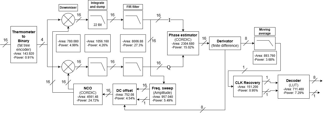
Carrier recovery works in two steps. A coarse frequency sweep steps the NCO in 100 Hz increments across the 19.5 to 20.5 kHz band while accumulating the filtered in-phase amplitude, and the DC offset module then refines the estimate to 1 Hz resolution by integrating the relative frequency over a thousand samples, locking once consecutive integrations agree. The NCO itself is a phase accumulator feeding a pipelined CORDIC rather than a lookup table, since the mixing frequencies and clock do not form a simple fraction, making the phases unpredictable.
Design Choices
The decimation filters are the classic spot for CIC filters, but those brought overflow and area problems. Instead the design uses FIR filters at comparable area, exploiting symmetric taps so only half the multiplications are needed and implementing those multiplications as shifted summations that approximate the ideal coefficients. The whole digital part synthesizes to 8.48 µW and 20,524 µm²; nearly all of the power is leakage, so at these low clock frequencies minimizing area and minimizing power are effectively the same problem.
Results
The full receiver decodes the target message essentially error-free at the specified 17.8 dB SNR and stays robust across carrier offsets over the whole 1 kHz band. Below that, degradation is gradual rather than abrupt, and in favorable runs even a 9.63 dB input decoded correctly.
Character error rate vs. input SNR (carrier at 20050 Hz)
| SNR [dB] | CER | Decoded output |
|---|---|---|
| 21.2 | 0.00% | An easy english text to check character error rate: CER |
| 17.8 | 1.82% | An easy english text to check character error rate: CER |
| 14.8 | 34.55% | An easy eng ish ext to check naaractererrot rete: CEC |
| 12.1 | 69.09% | An easy eng c ext to nhec nae aracter ot rote: IIS |
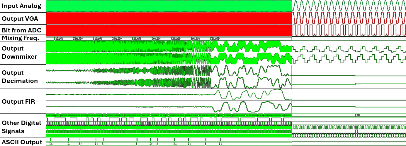
The mixed-signal simulation below shows the complete receiver in action, from the analog input at the top to the decoded ASCII characters at the bottom. The coarse frequency sweep is visible in the mixing frequency trace before the DC offset refinement takes over.